
650Vue Part 3: Modelling the KIM-1
I feel comfortable when working with 8-bit systems, but I like to think that this feeling is more than simple nostalgia or familiarity. 8-bit systems are simple; 8-bit systems are small. I can wrap my head around the constrained architecture and hold the broad landmarks of a 64Kb memory map in my mind. I can understand details, such as how the video display is mapped to memory, or how input from the keyboard is handled, or how the cursor blinks. Ask me how these low-level functions are carried out on a modern computer and I can't provide a good answer. In a way, this is the whole point of modern computers: all this low-level business has been abstracted away. We don't have to worry about these details anymore; we are free to write our Python scripts and our CSS, secure in the knowledge that the hardware will "just work". But to master the 8-bits, we must become familiar with their component systems.
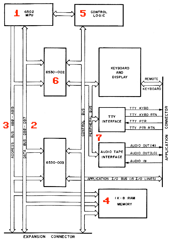
Figure 1 shows a rough schematic of the KIM-1's architecture, taken directly from the user manual. On this diagram, we can identify a number of features:
- The 6502 chip, identified as a MicroProcessor Unit (MPU). More sophisticated MPUs can have floating-point math co-processors, cache controllers, and memory management units, but the KIM-1's MPU contains only the 6502 Central Processing Unit (CPU). Nowadays, most people would simply call the 6502 a CPU and leave it at that.
- An 8-bit data bus, which represents 8 literal traces on the circuit board connected to 8 pins on the CPU. When we say a system is "8-bit", we're talking about the data bus.
- A 16-bit address bus that connects 16 pins on the CPU to the computer's memory through 16 address lines, which allow the 6502 to use a maximum of 64Kb of memory.
- A one-kilobyte RAM chip. Even though the 6502 can work with up to 64Kb, RAM chips were expensive in the 1970s, and the KIM-1 only came with 1Kb of useable RAM.
- A block marked "Control Logic" handles functions like starting and stopping programs, running in "single-step" mode, and what to do when the user presses the reset button.
- The two 6530 chips house the KIM-1's system ROM (all 2Kb of it), and handle functions related to timing.
- The peripheral bus allows the main computer to communicate with external devices such as a keyboard to collect user input, a TTY for output (either a teletype printer or a TTY-type video terminal), or an audio cassette player to store and retrieve data.
This brief overview of the KIM-1 omits a lot of detail—I've completely swept the control bus and the Input/Output (I/O) circuitry under the carpet—but it should provide a rough outline of how the components fit together. 650Vue uses a similar set of components as the KIM-1, although as I'll show below, they will be arranged in a slightly different configuration.
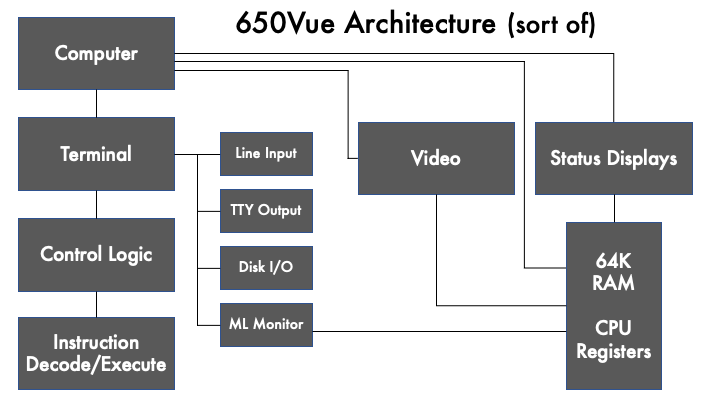
The diagram in Figure 2 shows the components that make up 650Vue. This diagram is not a formal dependency graph or entity relationship diagram; it's more a rough sketch of how I visualize the pieces fitting together. Even though Figure 2 is not completely accurate, it does show a number of points of interest:
- The Computer component (top left) doesn't actually do anything on its own; it's the root component that holds all the other pieces together.
- The Memory block (bottom right) houses 64Kb of RAM memory, as well as the registers of the 6502 chip. I model memory using Vuex to keep track of machine state.
- There are two Output Devices: a video display for program output, and a set of status displays that indicate various states of the 6502 processor.
- The Terminal component allows you interact with 650Vue. It connects to a set of virtual Peripherals: a line input for entering terminal commands, a "TTY" screen to display terminal output, a system for handling disk I/O (most modern web browsers don't know what to do with audio cassettes), and a Machine Language Monitor program that lets you write software and manipulate memory.
- The Control Logic component, similar to its counterpart in the KIM-1, handles starting and stopping programs, resets, and single-step execution.
- The Instruction Decode/Execute component simulates what happens in the 6502 chips as instructions are fetched from memory and carried out.
Because Vue's reactivity allows components to talk to each other, I did not need to build any kind of bus in 650Vue. I could have built a system where values get put on a data bus, to be routed to and from locations on the address bus, but I chose not to. I'm more interested in simulating the behaviour of a computer rather than emulating all of its components in precise detail.
I will talk about the technical details in upcoming sections, but before I do, I will talk about the visual design of 650Vue.